TABULA
Building instruction
Exploded drawing
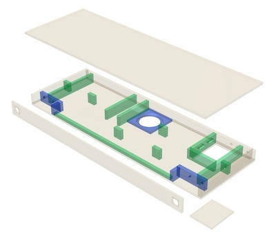
Exploded drawing

Assembly
The construction of the Tabula system is complex and, as a result of its flat design, difficult to build. Tabula is not recommended for beginners in loudspeaker construction with little experience in carpentry.
The construction phase assumes you have a very accurate hand-held circular saw with a guide rail or table-mounted circular saw, because DIY shops tend only to do parts down to 100 mm. In addition, you will need a router with a circular adapter and various router cutters (straight cutter, edge trimmer, cutters for chamfers and rounded edges), and a range of drill bits.
First, cut out the individual boards in accordance with the technical drawings. We recommend cutting all the holes and cut-outs before you glue boards together. The fitting of the fullrange BF 32 - 8 Ohm driver in the front panel is particularly critical and requires very fine carpentry skills. If no suitable tools are available, it is possible to proceed as follows for the 10 mm MDF front panel:
- Drill a 29 mm hole with a Forstner drill bit (or a smaller hole which you can then file to size)
- Make the recess for the speaker, e.g. with a carpet knife (small blade) and fine wood chisel
- Make the chamfer on the back using a rasp and file (this is necessary because otherwise the rear openings of the loudspeaker will be covered)
- Free up the terminal connections using a file
If you are planning any individual enhancements, this is the best time to make them. These might include a recess for an MP3 player in the lid, a cable cut-through in a particular place or grilles or covers for the loudspeakers. This is also the time to plan the paths for the wires to the wall. The drawing shows 10 mm holes in the rear for this purpose but they can be adapted to suit personal preferences.
To enable you to attach the individual drivers, terminals etc. easily at a later point, it makes sense to predrill the screw holes at this stage before gluing the parts together.
Once all the boards have been prepared, it is possible to start building. The Tabula has been designed to allow the base to be removed at a later time for any maintenance that may be necessary, so it makes sense to begin with the lid. Lay the parts on a flat surface and attach them one at a time (except the base) to the lid (marking the positions in advance may make this easier). Next, apply wood glue to the inner edges of the boards after they have been stuck together to ensure that the cabinet does not have any leaks later. Once all the joints have completely dried, mark the positions of the individual boards on the base, predrill them and countersink the holes so that the countersunk screws are completely flush at the end. One screw each should be enough for the strengthening struts (40 x 16 mm). For all the other boards, choose a reasonable number of screws to enable the base to be firmly screwed to the wall panels, strengthening struts and intermediate boards.
In the next step, you can start to lay the wires, which should have been ready made up and soldered to the crossover by now. The crossover can be placed between the cut-out for the mid-bass unit and the terminals inside the cabinet. Since the leads to the BF 32 - 8 Ohm fullrange drivers have to pass through small 7 mm holes, these will have to be sealed off later using hot-melt glue, for example.
The next step is inserting the damping material. Remember to keep back about a tenth of each mat per fullrange enclosure for later. The rest can be loosely distributed inside the cabinet. It makes sense to divide the mats into smaller pieces first. After this step, the base is screwed in place. If necessary, you can use a sealing tape to compensate for any unevenness.
It is now possible to start with the visual appearance of the cabinet(painting, applying film or other materials, varnishing...) and, after that, you can solder the W 100 S - 8 Ohm mid-bass unit to the two terminals and screw it in place. In the next step, we cut the M10 threaded rods to length. It is easiest if you first cut the 1 m rod in half and then, after the first trial run, cut it to the final length. The rods have to be well anchored in the wall (e.g. with construction glue) and then pass through the holes in the rear of the wooden cabinet as far as the inside of the two full-rangedriver cutouts. After the Tabula has been fitted to the wall by pushing it onto the rods, and all the wires have been connected up, it is firmly fixed in place using nuts applied through the holes for the fullrange drivers.
Inner damping
The provided damping material is distributed loosely inside the cabinet. About one tenth of the mat should be used for each fullrange speaker cabinet. The remaining portion can be cut into handy pieces and be loosely filled into the cabinet. It is important to ensure that the bass reflexport remains free of damping material.